The Wing
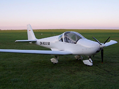
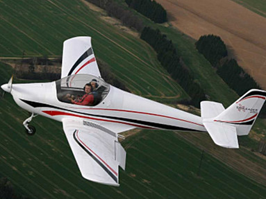
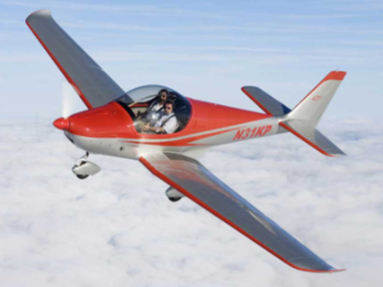
The all metal trapezoidal wing with two spar construction consists of the outer parts and the wing center section. The short wing center section is firmly placed into the fuselage. The outer parts of the wing are separable for transport.
Wing profile is GA (W) 1 at the root and the GA (W) - 2 at the tip. The main wing spar is placed in 33 % of the profile depth and is perpendicular to the longitudinal aircraft axis. The main spar is created from the dural beams and web. The beams are from metallurgical L – profiles, milled spanwise and riveted with web using full rivets. The web with changing thickness is relieved by the lightening holes spanwise. The ribs are stamped including lightening holes. The back spar is created by the L-profile and riveted web, which is relieving with lightening holes too. The cover is riveted with the pop rivets to the beams and the ribs. The flaps hinges are from dural sheets with milled grooves for flaps extending. Three safe attachment points attach the wing outer section parts with the wing center section.
Fowler Flaps
The flaps are of Fowler type with a proportional depth 29 % have 10° and 35° deflections. The flaps drive is mechanical in standard. The electrical system is available as an option. The mechanical drive system is created by toothed wheels with racks. The flap controller is placed in tunnel of the cockpit. Left and right parts of the flap drive are connected together. Flap construction is created by spar, ribs and cover, which are riveted with pop rivets.
The Aileron
The aileron is all metal with one spar. Construction consists of control rods and bent levers in the transverse control. The aileron deflections are differentiated.
The Wing Centre Section
The wing center section composed with two spars similar to the outer wing ones. These spars are firm attached into the fuselage construction. There are two fuel integral tanks in the front part of the wing center section, each one with 8.5 gallons of fuel capacity. The main landing gear is attached to the wing center section, so it creates an independent set, which can be moved at manufacturing or emergency transported during operation.
The Fuselage
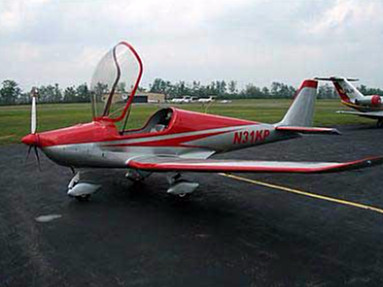
The all metal fuselage construction is created by dural L form stringers, by metallic bulkheads and by cover. The stringers are attached together through the whole length of the fuselage and create a base supporting system of the fuselage. A transverse cross-section of the fuselage is shaped so that the cover could be unrolled and so was stabilized for an increasing of a critical tension. In the cockpit area is the supporting system replenished by steely spar of the closed square cross-section - middle panel of the cockpit. The seats are lengthwise adjustable and equipped by 4 points seat belts. The canopy creates perspex, which is inset into fiberglass frame with reinforcement from carbon and cevlar fibers. The canopy allows a perfect view backwards. The control is dual with control sticks and pedals. The directional control is funicular with turnbuckles.
The Landing Gear
The landing gear is retractable, controlled by electric motor with manual emergency control. Fixed Landing gear is determined for the Light Sport Aircraft category.
Both wheels of main landing gear and the nose wheel are towed and they are sprung with rubber shock absorbers, created by circular rubber segments. The nose landing gear is at protuberant position connecting with the foot control and is controllable at +15° range. The main landing gear wheels are braked with a central manual hydraulic brake lever at the control stick.
The Engine & Propeller
The airplane is equipped with Rotax 912 UL (80hp) engine, optionally with Rotax 912 ULS (100hp) or Rotax 914 UL (115hp turbo) engine. The engine is attached by welded bed with the use of rubber shock absorbers through the firewall into the fuselage stringers and central tunnel. Three (3) blade on-ground adjustable propeller is delivered with the plane as standard. As the optional order can be airplane equipped with mechanically or electrically in-flight adjustable propeller, two or three blade.
The Tail Units
All metal tail units are standard alignment with a rudder and an elevator. The profile of Vertical Stabilizator and Horizontal Stabilizator is symmetrical to NACA 0012. They are created by spars, ribs and cover. An elevator is divided; therefore it is possible to take it down without disconnecting the controls. The same construction is used at the others control surfaces. A stabilizer is attached to the fuselage by four hinges and is possible to dismantle it without disconnecting the controls.
The Fuel Installation
The aircraft has two integral tanks with capacity of 2x32 liters (total 64l) of the fuel. Optionally can be installed the additional fuel tanks supplying the aircraft with additional 2x15 liters (total 30 liters) of the fuel. Therefore max. amount of the fuel should rise up to 94 liters. The tanks are created by lead box inside the wing center section, out of the fuselage. They are riveted through caulk mastic and the wing center section cover forms concurrently a tank wall. The fuel delivery is ensured by a pneumatic pump for the overflowing the system and in the reason of an error or delivery deficient of the pneumatic pump is possible to use an additional electric pump. A fuel amount is indicated by two analogue fuel gauges.
The Equipment
The aircraft is in UL category furnished with standard instruments for flight and engine control. The Radio, Transponder, Glass Panel, GPS or another flight and engine instruments are installed on the customer's request. Color painting, upholstery and internal cockpit surface adjustment of the aircraft is realized individually on basis of plentiful amount of offered services and products.


